


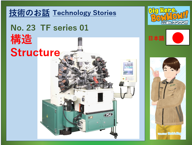
No.23 TFシリーズ 01 構造
もりおです♪
今回から、引張ばね加工機TFシリーズを扱ってみようと思います。
「ちょっと、ぼくには、まだ荷が重いよ」と、先輩方に抵抗&ヘルプ依頼をしてみたのですが、
「まあ、何事もチャレンジだから頑張って」と軽く突き放されてしまいました。
TFシリーズは、当社の顔みたいな商品でもあり、技術内容もたくさんあるので、
長丁場になりますが、脱線なんかもしながら、勉強していきたいと思います。
皆さん、見捨てないでくださいね。
では、まず機械の構造から始めましょう。
TFシリーズも工作機械なので、以下の基本構造を備えています。
1. ベッド(Bed)
土台となる部分で、工作機械一般では、鋳鉄や炭素鋼で作られています。
TFシリーズでは、炭素鋼を使用しています。
役割りは、
・機械全体を支え、加工時の振動を抑える
・フレームをしっかり固定する。
TFシリーズでは、本体フレームだけではなく、2次加工機も接続されます。
を担っており、機械の耐久性やばね精度の実現の根幹をなす最も重要な構造の一つです。
箱型構造で、リブと言われる補強材を使います。
2. フレーム(Frame)
フレームは、ベッドの上に配置され、加工ユニットを装着する部分です。
TFシリーズでは、前後2枚の構造になっています。
役割りは、
・各加工ユニットを安定して支える
・加工時の振動を抑え、精度を向上させる
・工作機械全体の強度を高める
3. 加工ユニット(Machining Unit)
加工ユニットは、ばねの加工を行うツールを装着する部分です。
TF本体には、以下の加工ユニットが搭載されます。
・送りユニット:ワイヤーを加工部に送り込みます。
・トーションアタッチメント:フックの曲げやボディーコイル部分を加工します。
・加工スライド:フックを起こしたり、切断をしたりします。
・プッシュピッチ:ばねにピッチをつける。
2次加工機には、以下の加工ユニットが搭載されます。
・アーム:本体で加工されたばね(後フック起こし部分が未完成)を2次加工機に移送します。
・ローターアーム:移送されたばねを適切な角度で後ろフックを起こす位置に回転移動させます。
・スライド:後フックを起こします。
このように表に見える部分と、サーボモーターの動きを表の加工ユニットに伝える部分(軸やギアなど)から成り立っています。
4. アタッチメント(Attachment)
アタッチメントは、加工の幅を広げるための追加装置です。
例えば、本体の前フックを起こす時に、ツールの動きを立体的にしたりします。
5.加工ツール
加工ユニットやアタッチメントに装着され、実際にワイヤーに触れて、加工を行います。
TFでは、以下のような加工ツールがあります。
・送りロール
・線ガイド
・曲げダイス(コイリングポイント)
・オコシツール、サポートツール
・切断刃、切断受け刃
・芯金
・ピッチツール
・チャック
6.制御装置
CPU、サーボドライバー、サーボモーターなどで加工ユニットの動きを司り、
データを適切に通信するための装置です。
TFシリーズでは、ベッドの中に入れる部分と制御ボックス部分があります。
(サーボモーターは、フレームに装着されます)
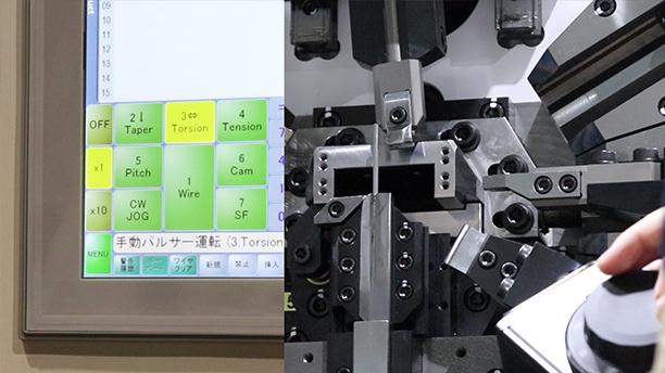
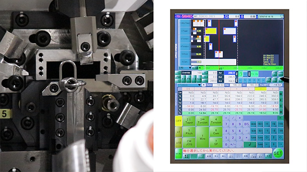
7.操作パネル
加工プログラムの入力や生産管理設定を行うモニターの部分です。
ベッドから連結され、タッチパネルとボタンの操作部とコンピュータで構成されています。
ここで作成されたデータが、制御装置に通信され、実際の加工ユニットの動きになります。
このほかにも、品質管理用のセンサーなども活用します。
初回ということで、簡単に全体の構造を説明しました。
今後は、いろいろと脱線しながら、詳しく見ていきたいと思います。
次回もお楽しみに!
※このブログは、生成AIを活用して作成しています。
No.23 TF series 01 Structure
Hi, it’s Morio♪
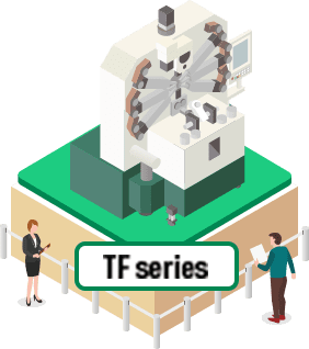
Starting from this post, I’ll be diving into our TF series for extension springs.
To be honest, I felt it was a bit too much for me, so I tried resisting and asking my senior co-workers for help. But they just brushed me off with “Well, everything is a challenge, so do your best!”
The TF series is one of our most popular products and involves a lot of technical aspects. This will be a long journey, but I plan to explore it while making a few detours along the way.
Please don’t abandon me!
Now, let’s start with the machine’s structure.
Since the TF series is also a machine tool, it has the following basic components:
1. Bed
“Bed” is the foundation of the machine. In general machine tools, it is made of cast iron or carbon steel.
For the TF series, we use carbon steel.
Its role includes:
Supporting the entire machine and minimizing vibrations during processing
Firmly securing the frame
In the TF series, not only the main frame but also secondary processing units are attached.
The bed is one of the most critical structures for ensuring machine durability and spring accuracy.
It has a box-type structure reinforced with ribs.
2. Frame
“Frame” is positioned on top of the bed and serves as the mounting base for machining units.
In the TF series, it consists of two plates, one in the front and one in the back.
Its role includes:
Providing stable support for each machining unit
Reducing vibration during processing to improve precision
Enhancing the overall strength of the machine tool
3. Machining Unit
The machining unit is where the spring processing tools are mounted.
The TF main unit is equipped with the following machining units:
Feed Unit: Feeds the wire into the machining section
Torsion Attachment: Bends hooks and processes the body coil section
Machining Slide: Lifts hooks and performs cutting
Push Pitch: Adds pitch to the spring
The secondary processing machine is equipped with the following machining units:
Arm: Transfers the spring (which still has an unfinished rear hook) from the main unit to the secondary processing machine
Rotor Arm: Rotates the transferred spring to the correct angle for rear hook forming
Slide: Raises the rear hook
The machining unit consists of visible components as well as parts that transmit the movement of the servo motors to the machining units, such as shafts and gears.
4. Attachment
Attachments are additional devices that expand the range of processing capabilities.
For example, one of the attachments enables three-dimensional tool movement when raising the front hook.
5. Machining Tools
Machining tools are mounted onto machining units or attachments and physically contact wire material to perform processing.
The TF series includes the following machining tools:
Feed Rolls
Wire Guides
Bending Dies (Coiling Points)
Lifting Tools, Support Tools
Cutters, Cutting Support Tools
Arbor / Mandrel
Pitch Tools
Spring Chuck
6. Control System
The control system consists of a CPU, servo drivers, and servo motors, which manage the movements of machining units and ensure proper data communication.
In the TF series, there are control components housed inside the bed as well as a separate control box.
(Servo motors are mounted onto the frame.)
7. Operation Panel
The operation panel is the monitor section where machining programs and production management settings are entered.
It is connected to the bed and consists of a touchscreen, button controls, and a computer.
The data created here is communicated to the control system, which then directs the actual machining unit movements.
Additionally, sensors for quality control are also utilized.
Wrapping Up
Since this is the first post in this series, I provided a simple overview of the machine’s structure.
Moving forward, I’ll be diving deeper into each topic while occasionally going off on tangents!
Stay tuned for the next post!
※This blog is created with the help of AI.